Cheap logic analyzer + PulseView + custom decoder works great!
- Derek Jamison
- Nov 13, 2021
- 3 min read
Updated: Nov 13, 2021
I found this KeeYees USB Logic Analyzer Device with 12PCS 6 Colors Test Hook Clip Set USB Cable 24MHz 8CH 8 Channel UART IIC SPI Debug for Arduino FPGA M100 SCM on Amazon for $14. "You get what you pay for"... the clips that come with it are cheap, so you have to cut off the ends of the cables and solder your own connections. Based on other people's review, I wouldn't trust the included USB cable for high-speed data but it worked just fine for my 800KHz test.
On my Windows 10 desktop, the logic analyzer device wasn't detected automatically so I used https://zadig.akeo.ie/ to install the WinUSB driver for the device. That also failed for some unknown reason (but at least the error messages along the way were humorous). After a "reboot and try again" the WinUSB driver installed fine.
My Windows 11 laptop running PulseView 64-bit and plugging in the logic analyzer just worked without me having to do anything!!! No idea why -- maybe because I geek out with it and have used RTL-SDR, other logic analyzers, etc. On another Windows 11 machine (not sure what build) it failed to install the driver & still failed after rebooting.
If you can get the drivers installed and don't mind cheap probes then it seems like an okay solution? (The other logic analyzer I have is $400 so $14 seems like a great deal.)
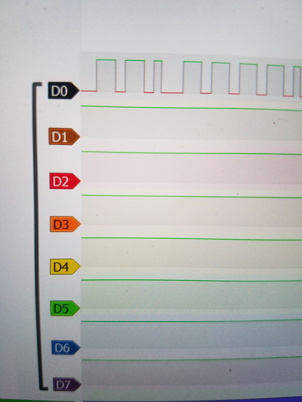
The device labels the pins CH1-CH8 (but PulseView uses D0-D7 notation). You can rename the pins in PulseView, but instead I choose to label the probes 0-7. The probes that come with the logic analyzer are two of 6 different colors each, so you end up with duplicate-colored probes. It also comes with 10 conductor wire which happens to have all of the colors of PulseView. You just need to look at the wire color (like "purple") and not the probe color ("red"); which should be simple enough. I wonder when I'll write a post about debugging something for an hour because I looked at the probe color instead of the wire color. 🤣
I ordered the wires in the order shown in PulseView (although you can reconfigure PulseView to use different colors). Here is a picture that describes the 1000 words above...

I had never used PulseView before but I really liked it. It only takes a few minutes to learn and it comes with a bunch of different sigrok decoders for various items you are likely to connect.
For my first test, I wrote an Arduino program that encoded the message "HELLO" using WS2812b lights. We end up with 5 lights representing "Hello".

When the Arduino runs the program above, it lights up the first 5 lights using the WS2812b protocol (the far-right light is the first LED -- with the intensity of 'H', which is not as bright as 'o' on the far left):

The community has written a bunch of decoders, so a WS2812b decoder already exists!!! We just need to configure the decode to know which wire we connected to the data line. In my case, the D0 probe was hooked up to the data line. At the bottom of the screenshot you can see the decoder showing both the decoded bits and the HEX codes that match our Arduino program! (Way easier than decoding the signals by hand.)

Next, I decided to try making my own encoding where I blink a normal LED (not WS2812b) really quickly, but the length of the pulses are based on the character we want to encode (so a 6.5ms pulse represents an A, a 6.6ms pulse for a B, a 6.7ms pulse for a C, etc. and the beginning of a message is 0.42ms pulse.) NOTE: The last line of the code is the delay, but all of the code in the loop runs which also takes a little bit of time (so my ".42ms" actually takes a little longer than I wanted -- although I suppose I could use the logic analyzer to measure the actual pulse time and decrease the d=42 value until it actually was measured as .42ms.)

The light was flickering, so now it was time to create my magic decoder ring...

Here is a screenshot of it all working (at the bottom you can see it decoding the pulse lengths back into characters)!

This was just a simple protocol that I thought would be a fun way of showing what you can do, but you can imagine writing it to decode your custom remote control IR signals or something similar as well.
If you haven't already tried out PulseView with your logic analyzer, then I recommend taking a look. If you don't have a logic analyzer but have things like a Raspberry Pi or Arduino, then I recommend buying this $14 logic analyzer to help troubleshoot and decode signals.


Comments